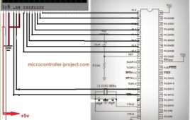
This project is about How to display moving-scrolling text/string on lcd using 8051(89c51 , 89c52) microcontroller. Moving or scrolling text on lcd is not very hard it is only the game of programming the more expert you are in programming the more you can do fun. It is same like we display moving text on our java applications or…
What is an embedded system?
If we look around, we will find ourselves to be surrounded by computing systems. Every year millions of computing systems are built destined for desktop computers (Personal Computers, workstations, mainframes and servers) but surprisingly, billions of computing systems are built every year embedded within larger electronic devices and still goes unnoticed. Any device running on electric power either already has computing system or will soon have computing system embedded in it.
Infineon boosts IPOSIM platform with automated lifetime estimation

Infineon Power Simulation platform (IPOSIM) from Infineon Technologies is widely used for calculating losses and thermal behavior of power modules, discretes, and disc devices. The platform provides easy access to analysis for single working points and user-defined load profiles. For industrial customers, estimating the lifetime of power modules is gaining more importance in the early…
FPGA vs microcontrollers: Another approach to embedded design
Most engineers start their journey in embedded systems with microcontrollers. With microcontrollers, one gets a complete miniature computing system on a single integrated circuit. The CPU, RAM, ROM and Input / Output peripherals all on a single thumb size SoC. This very popular approach to learning embedded design and development is in fact just the one side of the complete picture. Working with microcontrollers (and microprocessors) is all about software-based embedded design.
What are field-programmable gate arrays (FPGAs)?
Some of you may be familiar with the terms FPGA or Field Programmable Gate Array. And familiarity does not necessarily beget understanding. So what exactly is FPGA?In simple terms it is a logic chip which contains a two dimensional array of logic cells and programmable switches. They are ICs that contain an array of identical logic blocks with programmable interconnections.Just as on a blank canvas you can paint any picture you want, FPGA allows an engineer to design any digital circuit. They say: just generate the bit file, download it and you’re good to go! This is a big development over the traditional microcontrollers as the architecture of such controllers does not support larger designs. For example, microcontrollers like 8051 used Harvard architecture with CISC instruction set. FPGA does not have any inbuilt instruction sets which provide the designer with much greater flexibility. A controller has its own CPU which starts the controller, retains memory and performs several tasks. Unlike microcontrollers, a FPGA will not be able to start functioning on itsown due to lack of the traditional architecture.
Automatic door lock system using 8051(89c51,89c52) microcontroller
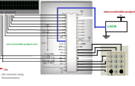
Automatic door locks are becoming popular in industry and many companies are using them to protect their valuables. In offices and homes automatic door locks systems are used for the safety of rooms and to allow only authorized persons to enter the office. Automatic door lock systems are also popular in banks. Banks use automatic…
Driving DC-motor in both directions forward and reverse using 8051(89c51) microcontroller and with l293d H-bridge motor driver
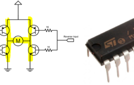
I this tutorial i am going to control the direction of dc motor using 89c51 microcontroller and l293d motor driver. Running a DC(direct current) motor in both clock and anti clock wise direction using a microcontroller is very easy. The only hurdle is that the dc motor requires more than +5 volt and nearly +100 mill Amperes…
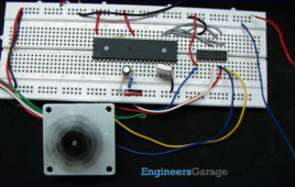
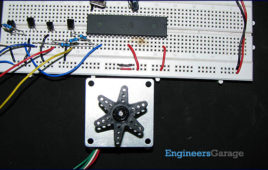
Interfacing Tower Pro SG90 9G servo motor with 8051(89c51, 89c52) microcontroller.
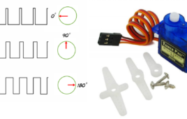
In this post i am going to teach you how to use and interface servo motors with 8051 microcontroller. 8051 series microcontroller which i am going to use for this project is ATMEL 89c52 microcontroller. Servo motors are different from ordinary motors. They can rotate from 0-degree to 180-degree depending on the motor specification. Servo…
Elevator(Lift) Controlled using 89c51 Microcontroller
This is a simple project on how to Control Elevator Lift using 89c51 Microcontroller? Tutorial is simple no interrupts of microcontroller are utilized for emergency situations or changing the floor during elevator movement. Once the floor is selected you can not change or deselect it. 8051 microcontroller general purpose input output pins are used to select the…
Serial communication data transmission to pc using USART of 8051(89c51,89c52) Microcontroller
This is a simple project on how to transfer serial data to PC(personal computer) using 8051(89c51) microcontroller usart(universal synchronous asynchronous receiver transmitter). Learning about 8051 microcontroller serial communication is the main task of the tutorial. Serial data can be transferred to PC(personal computer) using serial port of the computer. Serial port of computers are used to connect…
Digital clock with 8051(89c51,89c52) microcontroller 16×2 lcd and 4×4 numeric keypad
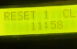
Here is a simple project on how to make a digital clock with 8051(89c51,89c52) microcontroller. The clock is efficient and their is no difference in time even in milli seconds. You can verify it with the digital clock you have. In the project i utilized the 8051 microcontroller internal clock source to produce a delay exactly equal to…
Push Button and Led interfaced with 8051 Microcontroller: Keil uvision
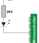
Here is a simple tutorial on how to interface a push button with 8051 microcontroller. In this tutorial i will teach you how to switch led on/off with push button press using 89c51 microcontroller. Push button with led is a beginners tutorial, who are getting started with 8051(89c51,89c52) microcontroller and keil uvision ide. Keil uvision…
Generating one second delay using internal timers of 8051(89c51,89c52) Microcontroller
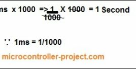
In this tutorial i am going to teach you about how to generate one second delay using internal timer registers of 8051(89c51,89c52) series microcontrollers. Normally we use for-loops to generate delay. The delay generated by running loops is arbitrary. No fixed time delay is generated by loops. Loops are only suitable if you want an arbitrary…
Counting on Led’s- Binary counter with 8051(89c51) Microcontroller
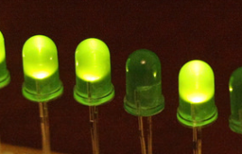
This is a simple and basic tutorial for newbies on how to display a counting pattern on led’s. Its going to be a simple binary counting on led’s. Recall binary numbers(00=0, 01=1, 10=2, 11=3 and goes on). Led’s will lit up in binary order. Led’s blinking pattern will be in binary form. Led’s will be…
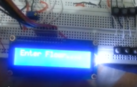
Interfacing 4×3 keypad and 16×2 lcd with 8051(89c51,89c52) microcontroller
In this tutorial i am going to explain how to interface 4×3, 4×4 numeric keypad and 16×2 lcd and 8051(89c51,89c52) microcontroller? Project function is simple when any one presses the button on keypad the particular character associated with that button will be displayed on the screen of 16×2 lcd. Project code is open source you…
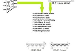
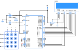
Interfacing ADC0808 with Serial port (RS232) using interrupt clock from 8051 microcontroller (AT89C51)- (Part 27/45)
In many applications data collected from multiple sensors is transmitted to PC for display or further analysis. The conversion of data from analog to digital form is done using an ADC. The digital data from the ADC is transferred to the computer using serial port. This circuit demonstrates the principle and operation of interfacing an ADC0808 with serial port of PC using the microcontroller AT89C51. The circuit is divided into three parts: ADC, controller and serial port. This circuit can be used as an intermediate circuit in many applications.ADC0808 which is an 8-bit resolution ADC has eight input channels i.e., it can take a maximum of eight analog inputs. The circuit uses the first analog input pin to take the analog input signals from the preset. To provide clock input to the ADC, Timer0 is used in interrupt enabled mode to generate a clock of frequency 500 KHz. To enable the Timer0 in interrupt enable mode, the register IE is loaded with the value 0x82. Every time the timer completes the counting, pin P1.2 toggles its state.
How to interface Serial ADC0831 with 8051 Microcontroller (AT89C51)- (Part 30/45)
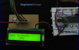
ADC is an electronic device which converts analog signals into its corresponding digital signal. This article demonstrates the principle, operation and interfacing of 8-bit serial ADC0831 with 8051 microcontroller.ADC0831 is an 8 pin IC with 8-bit serial data output (for more detail about ADC0831 refer to Interfacing ADC0831 with ATmega16). To receive the output from ADC high to low pulse is given at CS (chip select) pin of ADC form controller. ADC requires delay of two clock pulses before starting data conversion. At the second clock cycle, ADC sends a ‘0’ bit to the controller which indicates that the upcoming bits are the data bits.ADC needs eight clock pulses to send 8-bit digital output. This digital data is received bit by bit and stored in a variable. The data is converted to its corresponding ASCII value and sent to LCD for display. The connections of LCD with microcontroller are shown in circuit diagram. The analog signals are generated by at a variable resistance (preset) which is connected to input pin of ADC0831.
How to create custom characters on 16×2 LCD using 8051 microcontroller (AT89C51)- (Part 10/45)
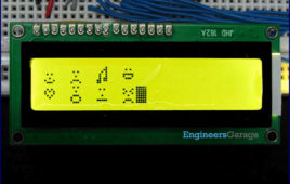
The commonly used 16×2 LCD can also display custom made characters besides numbers, alphabets & special characters. Any character can be made to appear on a 5×8 pixel matrix element without knowledge of its ASCII value. The idea explained here demonstrates the principle and operation of a simple LCD custom character display using 8051 microcontroller (AT89C51). When the ASCII code for any character, say ‘A’, is sent to be displayed on LCD module, the module’s controller looks up the appropriate 5×8-pixel pattern in ROM (read-only memory) and displays that pattern on the LCD. There are 8 symbol locations where a custom character can be stored as shown in the following right table. These locations will have a particular bitmap layout corresponding to the custom character. To display an arrow sign, the bitmap values are mapped to a base address location, say 64 (ASCII code 0).
How to control Stepper Motor using ULN2003 and 8051 Microcontroller (AT89C51)- (Part 17/45)
Stepper motor is a variable reluctance DC motor. When correct input sequence of signal is given to the motor, it starts rotation in steps. (For more detail refer Unipolar Stepper motor interfacing with microcontroller AT89C51). ULN2003 is high voltage, high current Darlington arrays each containing seven open collector Darlington pairs with common emitters. Here it…
How to interface Stepper Motor with 8051 Microcontroller (AT89C51)- (Part 16/45)
Stepper motor is one of the commonly used motors for precise angular movement. The advantage of using a stepper motor is that the angular position of the motor [[wysiwyg_imageupload::]]shaft can be controlled without any feedback mechanism. Stepper motors are widely used in industrial and commercial applications. They are also commonly used as in drive systems of autonomous robots.This article explains the unipolar stepper motor interfacing with AT89C51 microcontroller. The microcontroller is programmed to rotate the stepper in wave drive and half drive stepping modes. For basic concepts and working of a stepper motor, refer the article on Stepper Motors. A Unipolar Stepper Motor is rotated by energizing the stator coils in a sequence. In unipolar stepper, the direction of current in stator coils is not required to be controlled by the driving circuit. Just applying the voltage signals across the motor coils or motor leads in a sequence is sufficient to drive the motor.