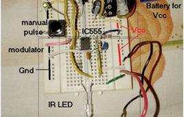
The circuit presented here is used to transmit and receive low frequency pulses using IR modulator and demodulator. IR modulator takes low frequency pulses as input. It modulates them on 38 KHz carrier and transmits them through IR LED as 38 KHz IR light. On the demodulator side IR sensor detects (receives) 38 KHz IR light. It demodulates this 38 KHz pulses and recovers transmitted low frequency pulses. One pulse generator is built using IC555 to generate low frequency pulses. IR modulator is also built using IC555 and TSOP1738 IR sensor is used as IR demodulator.
Automated Car Lightning System

Our governement has made rules that at night times if any vehicle is approaching from opposite side headlights of our vehicle should be dimmed to avoid focusing of . light on the driver in opposite vehicle inorder to avoid accidents . But, we ignore this which is cause for many accidents at night times.
Simple DC Motor Controller using 555 Timer IC

Controller is actually a combination of two circuits – driver circuit and Switching circuit. Driver is the actual circuit that drives DC motor and switching circuit decides how DC motor should be driven. So actually, switching circuit is the main circuit that controls the motor. Now there are two parameters of DC motor that can be controlled Speed and Direction.Changing the direction of DC motor is very simple just reverse the supply given to DC motor. For varying speed of motor you have to vary the applied DC voltage. One well known method widely used in industries is Pulse Width Modulated (PWM) speed control of DC motor also known as chopper control.
Panic Alarm

These circuit cost too less to your pocket as it made up of NE555 IC, buzzer , some resistors and capacitors. These circuit is also a user friendly. As with the help of just by one button pressing you will let other that you are in panicking condition without any difficulty.In these project astable mode of IC NE555 is used. Resistor R1 and R2 along with capacitor C2 used in the circuit so to tune the frequency. In the starting the circuit remain in the disable state. Now when the button is pressed the pin 4 and pin 8 of IC1 gets the high voltage. In turn of these the voltage at pin 2 goes down gradually and voltage at pin 3 starts increased in the same manner. And a situation arrives when the sound comes out from the buzzer.
Fastest Finger First Circuit using ATMega16
Fastest Finger first circuit is basically used in quiz type games where the reaction speed of a participant is significant. The circuit enables us to identify who responded first to the question by triggering a visual and audio indication. The circuit uses a buzzer to produce the audio signal and a seven segment display for visual indication. The display shows the corresponding team number which pressed the buzzer first. The brain of this circuit is an ATMega16 microcontroller which can run at a maximum speed of 16MHz and so there will be no question of clash between any two contestants until and unless their reaction time was same in order of microseconds which is impossible. Continue reading to find out what the circuit components are and how it is assembled as well as put to work.
Music Operated LED
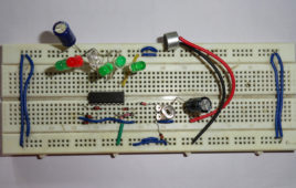
This circuit will light up different LED’s according to the audio signals which are feed through condenser microphone. When sound intensity is low few LED’s will glow as intensity of sound increases number of LED’s which glow also increases. Important feature of this circuit is we have not use any special running light IC like LB1405. We have made this circuit with the help of seven channel Darlington array IC ULN2003. ULN2003 is a monolithic high voltage and current Darlington transistor array. It contains seven NPN Darlington pair on a single IC. It also have high output voltage with common cathode clamp diode for switching inductive load. And collector current rating of each Darlington pair is 500mA. Another feature of ULN2003 IC it has 2.7kW series base resistor for each Darlington pair so that it can directly connected to TTL or 5V CMOS device. Read more to find out how this circuit is assembled and how it is made to work.
LED Constant Current

In the circuit when the voltage goes above 2V then at that time large current will pass through the collector of T2. And also the base current of transistor T1 goes up so that it can bring this transistor in the conduction stage. However at T1 transistor creates more and more negative. Exactly same thing occurs with the base of T2. And in turn of this T2 gradually closes and act against the starting growth of current. That how a steading effect achieved and we got a fixed value of current that will flow from LED.Rating of R in the circuit is equivalent with the LED current divided by 0.5
Clap Operated Remote Control for Devices
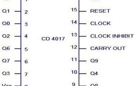
This circuit is based on two commonly used IC that is NE555 timer and CD4017 IC with few more components. 555 timer IC wired as an monostable oscillator. In this circuit NE555 monostable generates a clock for the circuit, which provide a oscillating wave to the output pin 3 of IC1. Monostable or one short multivibrator has only one stable state and we have to trigger it externally to return it back to its original state. CD4017 is a CMOS counter/ divider IC . It take clock signal from the clock input and turn on the 10 output in sequence, each time when it receives clock input pulses. It is the most popular IC and extremely useful in various project like Light Chaser, Matrix Die. In order to understand the working of IC one must know about its individual pin.
E-Toss

The project which is demonstrates a very interesting project of E-Toss. E-Toss is a very good option in place of coin toss. This project can also be used as game i.e. it can be played by two or more members and they have to choose whether a head or tale and press the switch. If the result comes out to be same what a player predict then that player won. This circuit can also be used in the games like cricket and many more where there is need to make any decision.
Adjustable Timer Circuit
This multipurpose adjustable timer circuit will give you alarm after every specific interval of time. You can vary the time interval with the help of 8 way dip switch. Therefore this timer can be used in kitchen, or by students preparing for competitive exam. As many of us have habit to forget, to switch off button of gas, electric oven which lead to wastage of resources and your hard work. Now with the help of this circuit you will receive an alarm after specific time so that you can remember to off the device. Some other features of the circuit are: You can also use it as alarm to switch off the motor because while watching TV or talking over phone we forget to switch off the pump in that case also it will give an alarm. You can set the time period for coking also like we used to in microwave oven.
Two Way Traffic Light
The project described below is a small model of traffic light which we daily see in our life on street. With this circuit you can control two way traffics. There will be lights on both sides, like there is red light on one side and green light will be present aautomatically on another side. It will also have yellow light to alert the passengers or drivers that now there signal are going to open.CD4017 is a 16 pin CMOS decade counter/ Divider. It take clock signal from the clock input and turn on the 10 output in sequence, each time when it receives clock input pulses.4072 is a dual 4 input OR gate. Output of OR gate goes high when any of the input goes high and if all input is low then output is also low7432 is a quad 2 input OR gate. In this also output goes high when any of the input is high and goes low when all inputs are low. 7432 contains 4 individual OR gate on single IC.
Call Indicator

This circuit is too much pocket friendly at the same time simple to build. 555 timer, capacitor, transistors, inductor and few resistors are needed to construct the circuit.When a new call coms this circuit will provide you aoptical effect by flashing of LED. In circuit is so much useful where you are not been able to put your phone in ringing volume viz: in the offices, in your house where your infant or your any people of your family sleeping and you don’t want to disturb them or else you even don’t want to listen your phone ringtone and need some silence in your home. You can also use this circuit in the place which is full of noise and mobile ringtone and you are not been able to hear your mobile ringtones, this circuit is too much useful for you in such situation.
Two Door Door Bell With Visual Indicator
The doorbells produce a ringing alert sound so that the resident comes to know that there is somebody at the door. Many homes have two doors for entering. So, sometime it become confusing for the resident to find out on which door visitor is present. This project on doorbell circuit produces two different sounds and can be used simultaneously on both the doors. This circuit also gives a visual indicator so that deaf person can also know. For this we use different color LED for different door so that it becomes easy to know whether the visitor is present on front door or rear door. This simple circuit is based on transistor, diode, resistor and switches with few more components. Resistor is a two terminal passive component used to control the flow of current into the circuit.
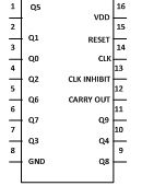
Radiation Sensor using 4033 IC
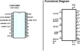
CD4033 is a Johnson counter IC commonly used in digital display. It has a 5 stage Johnson decade counter with decoder which converts the Johnson code to a 7 segment decoded output. This means it will convert the input into numeric display which can be seen on 7 segment display or with the help of LED’s.Advantage of this IC is it can be operated at high voltage of 20V because it is highly sensitive and it can detect EMF presence in the atmosphere and it is sensitive to static charge also.When you touch the input terminal with finger, counter get’s started.Therefore care should be taken while using it. It can be used in various applications like in 7 segments decimal display circuit, in clocks, timer etc.
How to Get an Organic Input Signal: Circuit to Detect a Living Organism

What is this? This is a device which will detect the organic living organisms when it is come in contact. It will send the signal in the form of electric current. If the organism is big enough, then the amount of current as a signal will found out the size of the organism. If the size of the organism is very big like an elephant then the amount of current will be very high. Oh…… this is a task to do. Let’s talk about how it actually works.How it works? I usually make very easy circuits for you so that very weak student in electric current can also be able to understand it and make it. So here it goes…..It only works with 2 transistors, both PNP and NPN. Just you should have two transistors and by connecting it in the particular pattern and then you will be ready with that.
Bell cum Light Controller

Many times it happen when somebody comes home in night and press the door bell, We search for the porch light switch. To identify that the visitor who as press the door bell is known or unknown person before opening the door. This circuit will help you to solve the problem. When a visitor press the doorbell switch it will automatically on the porch light after sometime so that when you reach near the door you don’t have to search for light switch. This circuit will automatically off the light after some time. This circuit also has the facility to on the porch light from inside the house. In day time you can off the light with the help of switch S3. Doorbell cum light has inbuilt doorbell so you do not require to purchase a door bell.
Heat Sensor Circuit Diagram
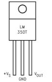
Heat sensor senses the heat present around the sensor. When temperature rises above the set value, it will indicate the presence with the help of glowing LED. This circuit can be used in kitchen or inside your PC. If your kitchen appliances or PC are over heated, it may be possible that it will damage the expensive components present in it. So to protect them from damage we have described a simple circuit which will give an indication when temperature around the sensor increases above the level set by you. This circuit is very small and can be easily install. In short, this simple project with easy to build electronic circuit is very useful to fight with problems like overheating.The circuit is based on two IC and few more discrete components.LM35 is a precision integrated circuit temperature and its output voltage is linearly proportional to centigrade temperature.IC CA3130 is operational amplifier which combines the advantage of both CMOS and bipolar transistor on a single chip.
Implemetation of BODMAS Rule using IC’s
Everyone has studied this rule in their childhood. It stands for “bracket, “off”, “division”, “multiplication”, “addition”, “subtraction”. A mathematical operation involve a number of operators but they must carry out in a particular order. The circuit described here will help you to practically implement the BODMAS rule which we have studied.The circuit is made with the help of three IC’s namely 7404, 7408 and 4073. 7404 is a hex inverter or NOT gate IC. It is a 14 pin IC and contain 6 individual NOT gate on a single IC. 7408 is a quad 2 input AND gate IC. It contains 4 individual AND gate on a single IC. 4073 is a triple 3 input AND gate. It contains 3 individual AND gate on a single IC. LED, switches and resistors are also used in this circuit.
How to display numbers and alphabet on 7 segment display?
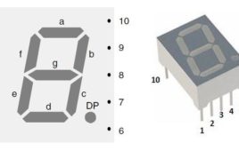
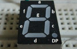
Seven segment displays nowadays are commonly used in place of dot matrix display. They have found their use in places like microwave or fancy toaster oven or the same on washing machine but before using them in all these places you need to interface the 7 segment display with microcontroller or some more hardware will be required. But with the basic knowledge of 7 segments display you can use it in front of your shop or you can display your name on it. 7 segment displays numbers from 0 to 9 and some alphabets.7 segment display are labelled a to g and decimal point is usually known as DP. DP is the common point. In common cathode display they are connected to ground and rest pin are connected to supply. Similarly in common anode DP are connected to supply and rest are connected to ground. You can also use more than one display according to your requirement.
How to Design a Variable Regulated Power Supply
The electronics devices works in dc power supply comes with different voltage specifications. Some devices works in battery power with voltages ranging from 1.5V to 9V, but majority of the devices can be directly plugged into a power plug. Such devices have a built in AC to low voltage DC converter inside it and the voltage output of that converter will be corresponding to the design of the entire circuit. The design of a circuit actually begins with considering the value of the voltage which will be supplied to it.The circuits which work in 5V power supply are most common which contains 5V TTL devices, but there is other category of TTL devices which works in 3.3V supply. Apart from these two categories there are CMOS based circuits and there is all kind of analog circuits which are designed to work on different voltages. Those who are interested in working with all these kind of circuits should have a variable power supply source.