
This Article is to make readers to explore about how Automatic Wiper works in modern cars. Here you can get an idea on the CAN Bus which is used in the Communication of Sensors, Actuators and controllers in a car.The CAN Protocol is in view of a bus topology, and just two wires are required for Communication over a CAN bus. The bus has a multi-master structure where every device on the bus can send or get information.
USING INTERRUPT TO READ DATA FROM CAN CONTROLLER IN ARDUINO

The Arduino board also includes pins which can be used as external interrupt pins. The interrupt is a method to divert the Arduino from current block code execution to do another block of codes that needs immediate processing. The block of code which is written to process by an interrupt occurrence is called an Interrupt Service Routine (ISR). The Arduino will stop its current processing and start executing the ISR once an interrupt occurs.
TEMPERATURE AND HUMIDITY SENSOR USING ARDUINO CAN INTERFACE

This article will give information about how Arduino ADC can be used to get the data from DHT11 Humidity and Temperature sensor and to transfer it over the CAN bus using CAN controller MCP2515. It will give you an in-depth idea about SPI interface with Arduino and CAN controller and Commands used for the configuration of CAN Communication.This project is designed to read Humidity and Temperature using DHT11 And transmitting by CAN protocol implementation. The Humidity and Temperature changes are measured by the ADC and transmitted to the other node using the CAN Bus and the data is received at the other node and displayed in an LCD.
CAN BASED INDUSTRIAL SERIAL WIRING SYSTEM

This Article is to explain some of the basics of CAN and show how choosing CAN for embedded systems networked applications beneficial.In today’s world, every industry need is automation so the industries will need automation, protocol, this project focused on a system in which CAN protocol is used to monitor and control 4 different devices by single Arduino called as master and another Arduino called as a slave.
Data logging In SD Card Using LPC1768- (Part 16/21)

This project is extension to the previous tutorial which explains how to interface the SD card with an LPC1768. Here we will program to log the temperature reading from a LM35 sensor to a text file periodically. The ARM Cortex M3 runs on 3.3V power supply with a built in crystal frequency of 16 MHz. A 32GB SDSC card from Transcend is used in this particular project, but the code will work with most of the SD cards. The SD card is formatted with FAT32. The ultimate aim of this project is to create a file in the FAT32 file system of the SD card. For setting up the Environment for the development of ARM cortex M3 is well discussed in this article.Insert an SD card into the card holder and upload the sketch to your LPC1768. If the sketch is able to write to the SD card OK, it will create a text file called ‘Temperature.txt.
SD Card Interfacing With LPC1768- (Part 15/21)

This project explains how to interface the SD card with an LPC1768. The ARM Cortex M3 runs on 3.3V power supply with a built in crystal frequency of 16 MHz. A 32GB SDSC card from Transcend is used in this particular project, but the code will work with most of the SD cards. The SD card is formatted with FAT32. The ultimate aim of this project is to create a file in the FAT32 file system of the SD card. The SD card has been formatted as FAT32 before interfacing. The generalized code for the FAT32 is written to interface the SD card.
USB HID Using LPC1768- (Part 18/21)

This is the article to explain the implementation of Human Interface device(HID) in the USB module of the LPC1768. For setting up the Environment for the development of ARM cortex M3 is well discussed in this article.The LPC 1768 is ARM Cortex- M3 based Microcontrollers for embedded application features in low power consumption and a high level of integration. The ARM Cortex M3 is designed in a such way to enhance debug features and a higher level of system integration.
USB Mass Storage In LPC1768- (Part 21/21)

This is the article to explain the implementation of mass storage in the USB module of the LPC1768. For setting up the Environment for the development of ARM cortex M3 is well discussed in this article. The ARM Cortex M3 is designed in a such way to enhance debug features and a higher level of system integration.
USB HOST Keyboard In LPC1768- (Part 19/21)

This is the article to explain the implementation of host keyboard in the USB module of the LPC1768. For setting up the Environment for the development of ARM cortex M3 is well discussed in this article.The LPC 1768 is ARM Cortex- M3 based Microcontrollers for embedded application features in low power consumption and a high level of integration. The ARM Cortex M3 is designed in a such way to enhance debug features and a higher level of system integration.
USB Virtual Comport Using LPC1768- (Part 17/21)

This is the article to explain the implementation of virtual COM-port in the USB module of the LPC1768. For setting up the Environment for the development of ARM cortex M3 is well discussed in this article.
USB Audio Using LPC1768- (Part 20/21)

This is the article to explain the implementation of USB Audio Device in the USB module of the LPC1768. For setting up the Environment for the development of ARM cortex M3 is well discussed in this article.The LPC 1768 is ARM Cortex- M3 based Microcontrollers for embedded application features in low power consumption and a high level of integration. The ARM Cortex M3 is designed in a such way to enhance debug features and a higher level of system integration. It clocks at a CPU frequency of 100 MHz, and incorporates a 3-stage pipeline and uses a Harvard architecture with separate local instruction and data buses for third bus peripherals.
Interfacing Servo Motor With LPC1768- (Part 13/21)

This project demonstrates the operation and interfacing of a servo motor, where the control signals for the rotation of the motor are provided by LPC1768 (ARM Cortex M3). The servo arm rotation is controlled by a potentiometer interfaced to the ADC of LPC1768. Starting from 0° as initial position it rotates to 180° as the potentiometer rotated from one position to other. For ADC interfacing with LPC1768 refer this article. For basic concepts and know-how of a servo motor, refer to the article Servo Motor. For setting up the Environment for the development of ARM cortex M3 is well discussed in this article.
Stepper Motor Interface With LPC1768- (Part 9/21)

This article explains the unipolar stepper motor interfacing with LPC1768 microcontroller. The microcontroller is programmed in two ways one is to rotate the stepper motor in sweep mode (i.e front and back) and another is to control the speed of rotation of the stepper motor. For basic concepts and working of a stepper motor, refer the article on Stepper Motors. For setting up the Environment for the development of ARM cortex M3 is well discussed in this article.
DC Motor Control using PWM of LPC1768- (Part 12/21)

In this article we are going discuss about the interfacing of DC Motor to ARM Cortex M3 (LPC1768). We are going to code the LPC1768 in such a way that the speed of the DC motor is controlled by the potentiometer connected to the ADC input and the speed is also displayed on the LCD. More details about ADC interface refer this article. For Setting up the Environment for the development of ARM cortex M3 go through this article. For detailed information about the ADC interface you can refer this article.
RTC Programming in LPC1768- (Part 11/21)

This is the article to introduce the RTC (Real Time Clock) programming of ARM Cortex-M3 LPC1768 Microcontroller. Here we are going to set the recent time and date in the RTC registers and retrieve it to display on LCD. For setting up the Environment for the development of ARM cortex M3 refer this article.
UART Programming in LPC1768- (Part 14/21)

This is the Article to introduce the UART (Universal Asynchronous receiver/Transmitter) programming of ARM Cortex-M3 LPC1768 Microcontroller. Here we are going to receive serial data from PC and echo back the same data while displaying the same on the LCD. Setting up the Environment for the development ofARM cortex M3 is well discussed in this article.The LPC 1768 is ARM Cortex- M3 based Microcontrollers for embedded application features in low power consumption and a high level of integration.
DAC Programming in LPC1768- (Part 10/21)

This tutorial will teach you how to use the inbuilt DAC of LPC1768 to generate a analog output (cosine wave) from a digital pin and display in the CRO. For setting up the Environment for the development of ARM cortex M3 is well discussed in this article.
ADC Programming in LPC1768- (Part 8/21)

This tutorial will teach you how to use the inbuilt ADC of LPC1768 to convert an analog voltage input to a digital number and display in the LCD. Setting up the Environment for the development of ARM cortex M3 is well discussed in this article.
Using External Interrupts in LPC1768- (Part 7/21)

This is the Article to introduce the programming of external interrupt in ARM Cortex-M3 LPC1768 Microcontroller. Here we are going to do input and output functions of GPIO of LPC1768. For better understanding we are going to use a button and the LED. Our idea is to program in such a way that when the button is pressed the external interrupt is triggered and the LED will be ON. Setting up the Environment for the development of ARM cortex M3 is well discussed in this article.
Web Controlled LCD Display- (Part 9/12)
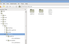
We will make a straightforward web application with a frame that permit a client to send a message to the Raspberry Pi utilizing Flask in a web browser. This will permit us to control the Raspberry Pi from a PC, tablet or smart phone. At the point when the form is submitted, it will send the message to the LCD by means of the Raspberry Pi’s GPIO ports. All the code, including the web application, is in Python and HTML.