In many of the applications it is required to alter the direction of DC motor instantly. Like in washing machine, mixer, drilling machine winding – rewinding machine etc. Changing the direction of DC motor using joystick is most suitable and handy method.In industries the joystick control is most preferable way to control machinery that is operated with DC motor. The best example is 3 axis or 2 axis DC motor operated crane. In this, 3 (or 2) DC motors moves crane up or down, rotate it left or right using 3 (or 2) joysticks
Intelligent LED light controller using AVR

Now a days LED light bulbs are becoming more and more popular because they have several advantages. Some of their advantages are listed below· Their energy (electrical) consumption is much more less· Their luminance is more· Their intensity can be varied· Their life time is moreSo if LED lights are used in place of conventional lights we can save much more electrical energy that leads to saving of conventional energy sources like coal, petrol, diesel etc. Also the light intensity of LED can be varied as per ambient light. That is one more plus point in saving electrical energy. We can set the light intensity to required level and get dual advantage of having exact amount of luminous and saving of energy.
4 Wire Touch Screen Based Digital Magic Slate
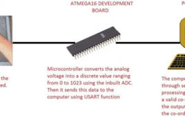
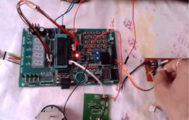
Ever played with magic slates in your childhood? Well this project will show you how to make a digital magic slate using a PC, a touch screen and few other components. Basically the project converts the analog voltage coming from the resistive touch screen into a two co-ordinate integer value and sends it to the PC through the microcontroller. The processing code takes these co-ordinates as inputs and draws a white dot for each co-ordinate, on the output screen.So when you write continuously on the touch screen, the dots would be plotted close enough to make it look like a line or curve. The circuit is based around a Atmega 16 micro controller, Serial to USB converter or (Serial to RS-232 + RS-232 to USB converter) along with a personal computer or a laptop.
Speed and Direction Control of DC Motor using AVR Microcontroller – (Part 20/46)

we can count number of such applications where there is a need to change direction and/or speed of DC motor. The direction of DC motor can be controlled by just reversing the polarity of given supply. And for varying speed, there are various ways to vary speed of DC motor but the best amongst them is PWM – pulse width modulation technique. In this technique we shall vary the width of applied pulse that will vary average voltage applied to motor and its speed will change.
LED Light Bulb Controller using AVR Microcontroller
Previously before 10-15 years the majority of electrical lights were either light bulbs (with yellow light) or tube-light sticks (with white light). The major disadvantage of these lighting devices was they consume more electrical energy (in terms of Watt) and gives less luminance (brightness). Light bulb wastes their most of the energy in form of heat. Also the life time of such devices was also short. Next comes compact fluorescent light (CFL) bulbs. They consume much less electrical energy than light bulbs and tube-light sticks and give more light. But their disadvantage is their intensity cannot be varied. Also their life time is limited to few thousand hours. But because their energy consumption is very less compare to light bulbs, they almost replace them.Now a days LED light bulbs are becoming more and more popular because they have several advantages over light bulbs and CFL bulbs. Some of their advantages are listed below
Accelerometer Based Hand Gesture Controlled Robot
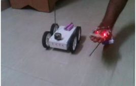
In many application of controlling robotic gadget itbecomes quite hard and complicated when there comes the part of controlling it with remote or many different switches.Mostly in military application, industrial robotics, construction vehicles in civil side, medical application for surgery. In this field it is quite complicated to control the robot or particular machine with remote or switches, sometime the operator may get confused in the switches and button itself, so a new concept is introduced to control the machine with the movement of hand which will simultaneously control the movement of robot.
Speed and Direction Control of Stepper Motor using AVR Microcontroller- (Part 25/46)
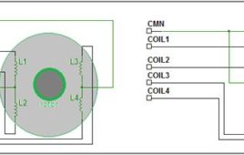
Stepper motor can be termed as digital motor because it operates on pulses. Unlike AC or DC motor that rotates continuously, stepper motor rotates in steps. It rotates in number of steps as per applied number of pulses. The common terminal is connected to –Ve (Gnd) terminal.So as we apply this four steps sequence continuously, the motor will rotate clockwise or anticlockwise. Now to change the speed of motor we have to change pulse repetition frequency (PRF) that is the frequency of applied pulses. If PRF is increased the pulse duration decreases and speed increases and vice versa. So this project demonstrates how to vary the speed and change the direction of given stepper motor using AVR microcontroller ATmega32
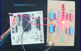
Controlling RGB LED colour using Atmega16- (Part 19/46)
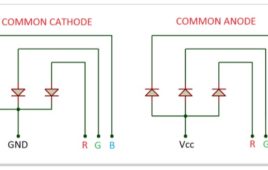
This tutorial will give you a brief introduction to the concept of colors and how different colors can be produced using RGB LED. The color would be controlled using an ATMega16 microcontroller.RGB LEDs are basically the combination of the 3 LEDs (Red, Green and Blue) fused into a single package. It consists of four pins totally out of which three of them for the three different colors. The 4th pin is common for all three colors and it’s either Cathode or Anode.
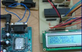
Latitude & Longitude Display System Using GPS & AVR Microcontroller- (Part 44/46)
This project is a reference to budding engineers or a helping hand to those who willing to work and interface a GPS Receiver with microcontroller and making their own channel to communicate with satellite, seeking for some useful information from satellite to make a effective and efficient system. Before we check all the details of this project, here is the final implemented circuit diagram of longitude and latitude display system using GPS and AVR microcontroller.
AVR I/O Ports- (Part 3/46)
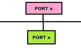
AVR microcontrollers are the advanced microcontrollers.Mainly the AVR family is sub grouped as ATmega, ATtiny, Xmega, UC3, SAM3 and SAM4. In these form 8 to 32 bit controllers are available. All the controllers having some common and some different features, those are coming to common features all are having I/O ports, timer/counters, interrupts and etc, coming to special features those are A/D converters, PWM, D/A converter, on chip I2C, serial communication interfacings, on chip EEPROM and etc. we can use all these features according to our requirement by programming. First we have to discuss about I/O ports. Generally, AVR microcontrollers having four I/O ports named as PORTA, PORTB, PORTC, PORTD. Take example as ATMEGA8 or ATMEGA 16 or ATMEGA32 microcontrollers, these are any having four I/O ports and each port having 8 I/O lines and totally each controller having 32 I/O lines.
Interfacing 4-wire Resistive Touchscreen with ATMega16 Microcontroller- (Part 46/46)
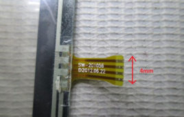
In this tutorial we’ll learn how to interface a 4-wire Resistive touch screen with ATmega16 microcontroller. Touch screens are two dimensional input devices. Nowadays most of the electronic gadgets use them. Laptops, smart phones, tablets and even some home appliances like washing machines & microwave ovens also use a touch screen nowadays. Touch screens are preferred over keypads because they need very little or no pressure to operate whereas the Keypads/ buttons need a minimum pressure to operate and our hands start aching after some time of continuous usage.One more great advantage in using a touch screens is that it enables us to make more room for the screen itself instead of wasting the space on the permanent keypad. That’s the reason for our smart phone’s screens to become big enough to browse web pages also and still fit in our pockets.
Smart Home Automation using AVR
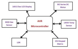
In this technological world, automatic systems are being preferred over manual system. In this series Home Automation plays an important role for humans. In this unit we talk about basic needs to understand the project well and also for its future advancements. We are going to talk about different types of sensors (i.e. Temperature Sensor, LPG Gas Sensor, LDR) and input and output devices (i.e. 2×2 matrix Keypad, Buzzer, DC Motor, 16×2 Char LCD Display, Power Supply section etc.).Now we are going to Interface all those with the brain of the system ‘Microcontroller (i.e. ATmega16/16L)’ and let’s find out what the individual role of each component are and how they act as Smart Home System together. In this project I used three analog sensors i.e. Temp, LPG Gas and LDR. These are given analog output. Read more to find out how the circuit looks like and what is the code.
Electronic Voting Machine using Internal EEPROM of AVR
The microcontroller based voting machines made the process of voting and counting the voted lot easier than before. Previously the votes were marked in paper which are then stored safely in a box and inside a well secure room for days. The process of separating the votes and counting them manually may take a lot of days. But after finding the electronic voting machine the votes can be marked without using papers, which makes the voting process eco-friendly. Moreover it makes the counting process faster and the results can be announced in a comparatively shorter period of time. There should be a controller inside the Electronic Voting Machine (EVM) which controls the process and there should be storage medium where the details of the vote are stored. There should be a ballet unit which is been used in such a way that the one who came to cast the vote can do only one vote.
LCD Scrolling Display Module- (Part 30/46)
A microcontroller is a device which has an inbuilt processor surrounded by few dedicated hardware modules. Once the microcontroller initializes them they start operating on their own. In case of an ADC it will do the sampling and digital to analog conversion all by itself and keep the converted data in its buffer so that the microcontroller can read that later. The advantage of this kind of implementation is that the microcontroller is free to do other tasks during that time and hence increase the overall efficiency. That was the case of hardware modules or peripherals inside a microcontroller which increases the processing efficiency of the built in processor. The efficiency can increase even more if the external hardware attached to the microcontroller can also does lot more tasks by their own without depending the microcontroller.
How To Write a Simple Bootloader For AVR In C language- (Part 35/46)
The Boot-Loader is a code which executes when a microcontroller is powered ON or reset. It basically sets an environment for the application code to execute. It is the Boot-Loader that sets the hardware and loads the application code from any storage medium or received through external communication and let the application to execute. Thus a Boot-Loader has to perform the following basic function : Initialize the controller peripherals, Initialize the devices in the board, Allow an option for the user to select from the available applications to load, Load the selected application, Let the application code to execute. Apart from the above mentioned functions some Boot-Loaders can perform many other functions and there are Boot-Loaders which don’t perform all these functions like provide option to select the required application etc. The Boot-Loader codes in microcontrollers are actually very small and simple compared to the Boot-Loaders in advanced devices like PC. In most of the microcontroller the functionality of a Boot-Loader is limited only to set the initial clock and other settings for the microcontroller, load an application binary from the serial port etc.
Arduino : What is Arduino
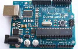
I was surprised to see a twelve year old boy giving life to his electronic gadgets. He was trying his hands on building his own creative toys which involved hard electronics and software skills. My zeal was on its peak to know the magical power inside the young chap. How did he understand the concepts of electronics so early? How did he develop the software? Anxiously I went down and asked him about the magic he was doing. The answer was Arduino. Arduino is an open source electronics platform accompanied with a hardware and software to design, develop and test complex electronics prototypes and products. The hardware consists of a microcontroller with other electronic components which can be programmed using the software to do almost any task. Learn more about open source hardware and open source software.
AVR ATmega16/32 Fuse Bits

Summary Updating with the era of technology, the new microcontrollers are coming with lots of inbuilt peripherals and features. These inbuilt peripherals and features not only reduce the cost of additional circuits to be used with the controller but also provide an ease to interface additional devices (such as Modems etc) directly with the microcontroller. The…
How to interface GPS with AVR microcontroller (ATmega16)- (Part 43/46)
GPS modem is a device which receives signals from satellite and provides information about latitude, longitude, altitude, time etc. The GPS navigator ismore famous in mobiles to track the road maps. The GPS modem has an antenna which receives the satellite signals and transfers them to the modem. The modem in turn converts the data into useful information and sends the output in serial RS232 logic level format. The information about latitude, longitude etc is sent continuously and accompanied by an identifier string.This article shows how to interface the GPS modem with ATmega16 and extract the location (latitude and longitude) from the GPGGA string and display it on LCD. The connection of GPS modem with AVR microcontroller (ATmega 16) is shown in the circuit diagram. The ground pin of max 232 and serial o/p of GPS modem is made common. Pin2 of MAX232 is connected to pin 3 of GPS modem and pin 3 of max 232 is connected to pin 2 of modem. This type of connection is called a serial cross cable.
AVR ATmega32 TWI Registers
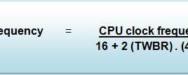
AVR (ATmega32) contains some in-built registers for TWI communication which not only reduce the level of complexity but also make the whole communication process smooth. These registers have been explained in this tutorial. 1. TWBR (TWI Bit Rate Register) : TWBR7 TWBR6 TWBR5 TWBR4 TWBR3 TWBR2 TWBR1 TWBR0 This register is used in master…
How to configure Watchdog Timers of AVR Microcontroller (ATmega16)- (Part 15/46)
Some high end applications require multiple or critical calculations to be done by the microcontroller. This may lead to cases when the controller enters intowrong or infinite loops. As a result of this, the system either hangs up or gets crashed. The solution to overcome these situations is to automatically reset the system whenever such a situation arises.The Watchdog Timer is a hardware or software generated timer interrupt which reboots/resets the system in the situations mentioned above. The watchdog timers are also used in cases when you intentionally require resetting the system without any physical interference.The AVR microcontroller has an in-built watchdog timer. This article explains the working of watchdog timer in ATmega16. The Watchdog Timer is a special timer which can be enabled in any section of the code and when enabled it ensures that a certain number of instructions execute within a pre-defined time frame. This time frame or the time delay can be configured/set using the registers of the watchdog timer.